Hi all,
I recently found out I have some kind of a strange fuse box wiring. Not a problem ... until ... you actually want to start measuring consumed and generated power (solar PV). I have seen several posts on this topic (for instance http://www.rowetel.com/blog/?p=135 and http://www.flukso.net/content/seperating-household-consumption-and-gener...), but I just wanted to share what about 20-25% people here in Belgium are experiencing.
In the drawing below, you'll see that you simply cannot physically connect the current clamp in such a way that you'll see exactly what you produce and/or what you consume. As mentioned in the last link, you simply cannot derive this by means of simple mathematics, since current clamps do not measure the direction of the current flow (it took my ages to understand, even though I have studied a number of years :-) ).
As depicted in the drawing here below, the points on the 300mA ELCB might - in 20-25% of the cases - be sealed.
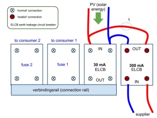
I have been told by an officially recognized inspection body that you are allowed to actually unseal the OUTPUT of the ELCB.
Next step of course is to connect solar power to the 300mA ELCB output.
The current clamp (1) can be left at the same place. Indeed by doing so, the current clamp would only read consumed power!
Regards,
Johan
At the moment I changed the "connection rail"... (mind you it's a 3fase connection rail in my case)...
also the connection rail connected to my "sealed ELCB" side...
also "sealed" in my Belgian case means that the 2-4 cables from the supplier are connected and even has a "chain"-link to show "tampering" if worked at (it will break...like a warranty if void sticker)
<---- street/fusebox <----- PV <---- CLAMPS <--- consumption
so when you remove the connection rail and use proper (thickness!)) cabling... you can put your clamps below the 30ma fuse...
the one that goes to your consumption...
indeed, that's another solution, but I had some bad experience with these connection rails before, so I'm not to keen on modifying them :-)
On the new F2 you can use multiple clamps or inline kw/h meter with pulse o/p
I had one clamp originally (now on a kw/h meter)on the output from the solar. The 2nd clamp is on the position [1] above.
On the graph this shows consumption and generated power as 2 graph lines.
I am now using the orig clamp on the mains lead to the mains switch to show the differential between solar and mains consumption.
(differential multiplier not set accurately yet)
http://i8.photobucket.com/albums/a19/bazzslk230/Flukso/FluksoJan15th12.jpg
http://i8.photobucket.com/albums/a19/bazzslk230/Flukso/Graph1.jpg
Bazzle