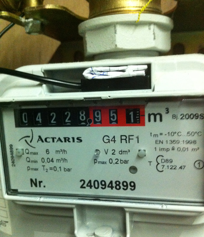
Till now, I have not been able to get any readings out of my Gas meter (Actaris G4RF1). First, I thought something was wrong with the contact, or the device. But after shorting the port I got readings, the same with using a magnet to generate a pulse. So I may assume a defect is ruled out.
Putting the sensor in front of the glass does not solve the problem either.
When the meter is running, I can see a small shiny square passing by on the second digit after the comma. Is this the magnet, or is this something else?
I'm out of clues now, maybe someone else can point me into the right direction?
Thanks.
edit: typo
| Attachment | Size |
|---|---|
| gas_meter_actaris.jpg | 178.65 KB |
Same problem's with same G4RF1 (sibelga -Brussel)
is this the solution with an other type G4 good? answer: https://www.flukso.net/content/actaris-g4-pulse
*Gas meter sensor is up and running. Simple reed switch inserted in the opening below the (red) digits and filled this up quite nicely with a piece of gum.
Wired it up to input 4 and entered 10 (liter per pulse) as the meter constant*
somebody can confirme if it work ? parameter? position?
Hmz, I must have overlooked that post you've mentioned.
Maybe I'll give it a try. Would be nice if I could get it working. Then only the water metering need a solution.
Ah, no. I've responded to early.
I'm pretty sure I'm needing an optical solution instead of a magnetic one.
Can somebody confirm this?
I have the same gasmeter then you David, but mine has only 1 impulse/0,1m³ !! The magnet is also very weak because the reed switch i tested with was not sensible enough, with an compass it seemed ok, but i detected no impulses. On the 0,001 m³ ring (third one) there is an mirror like thingy on the number 6.
So, i think i need also an optical sensor too.
On the other hand, the original 0,1m³ impulse resolution is much to small, 0,01 is better, 0,001 is best ;-).
It worked very well with a opto-sensor. See how i fixed-it a few day ago, here :
http://ubuntuone.com/5K0bD4UERyf6r9tzNjAabj
Because the tension of the sensor i used was working from 3.3V tot 5V, i put in serie resistance of 100 ohm in the wire who supply Vcc, so i lowered the current from 22mA to 14mA witch is better i think. The FLM02b is supplying a 5v voltage, so i used it.
Sorry the link above don't work, here is a new one:
http://ubuntuone.com/7QPVS7Jkk7ciSlds8gkAFI
That looks nice!
As I am a noob on this matter, how can I become the same result ;)
Here I showed also the same solution:
http://userbase.be/forum/viewtopic.php?f=88&t=39962&p=526819#p526819
The opto-sensor came from here:
http://www.ebay.com/itm/TCRT5000-Infrared-Reflective-Photoelectric-Switc...
If the FLM Vcc output on pin 6a is +5V and on pin - (on any free sensor input) than i advise to put a serial resistance of 100 ohm to lower the current to 14mA (otherwise it is almost to it's max 22mA).
The Digital out of the opto-sensor (= after the comparator) you connect it on the + of the FLM's sensor input).
In front of the digit you will detect the mirror on number 6, I advise to unglaze a little the glass (plexi) because otherwise you get to much reflexion.
The you make a support for it like i did. I used a piece of angled pvc that a screwed in the rectangle little hole on top of the space you put your reed contact in the picture above here in this topic.
If you want the dimensions of it, give a reply ;-)
Success ...
Thanks!
I've just ordered one. Looking forward to finally see the gas usage being tracked.
Hello David, leave a reply after you done the installation :-)
Hi,
I finally received the opto-sensor.
I already have one question. You mentioned I should unglaze the plexi a little bit. But what do you mean with that?
Use very fine sandpaper (600 - 1000) or something like this and go gentle over the plexi right in face of the digit with the mirror. Just a few square mm are enough. Look at my photo.
Just a little bit and test it when you turn the potentiometer. Of course when the digit is running :-)
When the pulses are detected turn right and left to the points where the pulses are stopped, then you choose halfway of those points. I hope you shall understand what i'm writing. Otherwise ask me in Dutch.
Have you put a serial resistance of 100 ohm in between of the + (pin 6a) and Vcc of the sensor ?
Digital puls output of the sensor is at the + of one pulsport, Gnd is at the - of the same pulsport.
Succes
Fluc
Ah ok, I thought I had to drill a hole in it ;)
So, now I only have to buy some wire and a resistance.
Could I perhaps use a UTP cable for the wire part?
I'll let you know when it is working (or not).
Thanks already for the help!
The resistance is just to lowering the current delivered by the output 6a from 24mA (max allowed) to 14mA.
Yes, you can use Utp cable and you can soldered it to the 3 pins, but don't cut the copper wire when you dismantle the isolation. Perhaps it is better if you use supple utp cable, rigid wire can sometimes break at the connections if not done carefully.
Ok so I ordered the goodies.
I've ordered 2 to have a backup.
My watermeter is already monitored by my flukso.
So can you check what kind or resistance I need to order as well?
A scheme on how to connect the resistance would be nice as well.
Now just wait and see when it arrives.
I don't know you have a FLM version 02a or 02b.
Can you check the voltage between connector 6a and the - of a puls input, the one that is free of course.
I think for version FLM v02a it is 3,3 volt DC and for FLM v 02b it is 5 volt DC, but i can be mistaken.
If you have a version 02a, no resistor should be needed.
Later i can place here the scheme. I don t' have this on file right now, just in my head.
I have a flukso 02a so I should be good to go.
A scheme would be nice :)
The settings in the flukso are 0.6 per tick if I'm not mistaken?
Can you measure the voltage to be sure ?
What do you mean by the 0.6 per tick ?
The meterconstante for your gasmeter is 10L / pulse.
aha... Well I was going by the markings on the meter itself.
I'll measure them to be absolutely sure.
Thanks for your help on this.
Nota bene: If there is one mirror on a cog wheel then regardless of where it is placed (on the zero or on the six, for example) there is one and exactly one impulse per rotation...
Hi Dieter, here the link to the scheme:
http://ubuntuone.com/4OILFH2lvB2iRqTl04FYcp
Hi Markus, yes there is one impulse per rotation, but in the FLM the meterconstante depends on the quantity you get per rotation of the cog wheel. With Dieter it is 10 L / rotation = / pulse.
Sorru Dieter, Hmmm, i provided the wrong scheme :-)
Here is a better one:
http://ubuntuone.com/1zxMLwNS8S0MMacw2ktOOA
How it is possible that i cant't edit my last topic post anymore :-(
I think a lot of users have this same problem...
wow cool Fluc!
I just got confirmation that my devices were shipped.
You are using normal utp cabling right?
I'll measure the volt this weekend to make sure I need the resistor or not...
You can use any cable, only 3 thin wires are needed. Telephone cable is also ok.
Same problem here: Actaris G4 RF1 not registering ANY pulses.
Putting it on the glas below the red digits did not work either.
btw: Actaris G4 RF1 is NOT THE same as the Actaris G4!
How can I TEST that my SENSOR (hardware sensor and the software config) are OPERATIONAL before resorting to other solutions??? Not a single puls registered on GAS nor Water probe!
@Gentleheart.
Just get a weak magnet and gently tap near the probe a few dozen times. Check the 'day' count on the flukso page after about 5 minutes.
You can also short the wires out in the same fashion to check the port is configured. (which you have to do in the Flukso set up page for sensor type, elctricity, gas or water...192.168.255.1)
I tested the probes with a magnet and both probes are working. Thanks for that tip. The problem is they SHOULD HAVE WORKED with my gas meter according to the website but now I have 2 sensors I paid for that are utterly USELESS.
Flukso still hasn't bothered to respond to this issue that I emailed to them, which I find &€&¥! They were quick enough to mail me for payment after putting in the order.
Fluc,
I have the opto-sensor, I had bookmarked your scheme, but I see its gone from the internet. Do you still have that ?
Thanks !
https://www.dropbox.com/s/1m7w2zb13t2n6y5/FLM%20to%20sensor.pdf
I put it in my other cloud, Ubuntu One has stopped.
Works ! Didn't even have to unglaze anything, just works ! Now just build a little plastic cap over the sensor, and I'm done. Thanks everyone ! (especially Fluc)