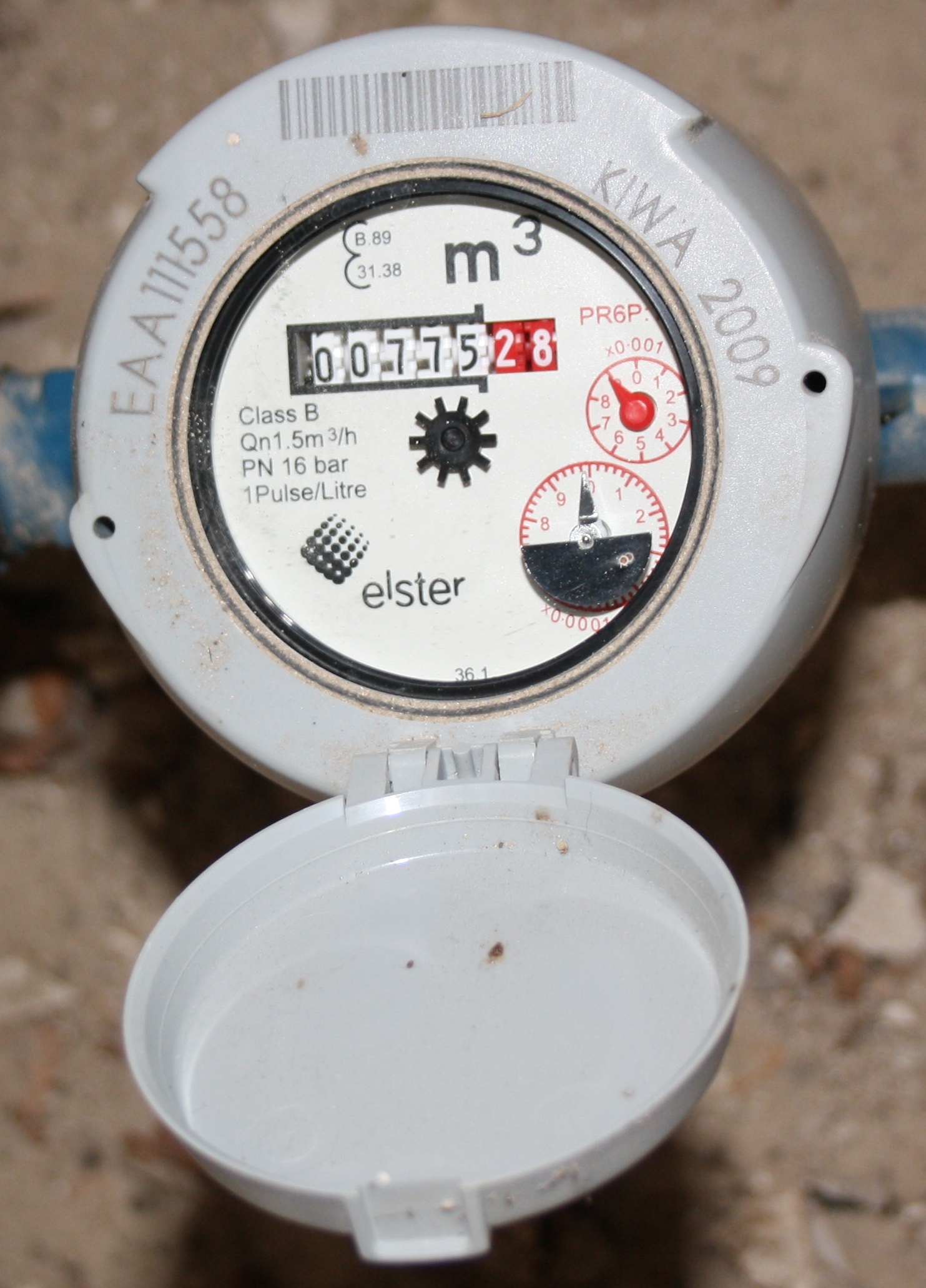
Can anyone tell me where to put the water probe FLS02-T1 (with Flukso V2b) on the meter in the photo? (= Elster PR6P:1)
Cannot find where to put the probe. There seems to be no hole or probe-input anywhere on this meter.
Second question: The cable on the sensor is too short. Can one extend this cable another meter with regular telephonewire or is this special wire?
Another Q: the whole meter and plastic cover can TURN 360 degrees. Is that normal?
| Attachment | Size |
|---|---|
| IMG_0046.JPG | 942.88 KB |
Another question for this posting:
The cable on the sensor is too short. Can one extend this cable with regular telephonewire or is this special wire?
The wire can be extended with nearly any type of wire pair.
For this type of watermeter, there is no magnet inside i think, you need a optical sensor.
The black half circle you see on the pic is the one to detect. 1 rotation = 1 litre.
OK, i see you posted questions already in other topic's for a solution ??
Relevant link:
https://www.flukso.net/content/water-probe-wire-length
I ordered the optical sensors for water and gas. Too bad flukso states on their website that the probes from flukso are compatible with o.a. the arcadis g4 rf1 dince it is not. Now I have paid for 2 sensor probes I cannot use. Support didn't respond to my mail about this.
I hope the optical sensors will work.
You saw on my pictures how i have installed the sensors ?
You need 3,3 to 5 V DC power for the sensors. The + 5 volt on pin 6A of the Flukso don't provide enough current for two sensors. You can use the power from for ex. an old nokia gsm charger, or like i did use the 5 V usb output from your modem/router if it is nearby...
With the sensors there is no connector provided, so you have to solder the wires on the pins or by a connector in a electro-shop.
I ordered also two spare optical sensors, you never know what to log in the future ;-)
I found the pdf with the scheme. Thx!
I just received them.
Question to fluc:
Can I connect 2 optical sensors after the resistor for power, provided the other 2 outputs are connected to a different port on the flukso? Or do I need put in a different resistor when using 2 sensors?
I used to be able to calculate this stuff in my sleep, but it has been too long ago...
What do you mean with:
provided the other 2 outputs are connected to a different port on the flukso ?
When connecting just one optical sensor you use 1 resistor in serial with positive connected to port 6a.
When connecting more optical sensors you use for them a external power supply of 5 V dc.
A resistor is then not needed but advised, so each sensor has a resistor of 100 ohm.
If you will, i can make a scheme for let's say 3 sensors ?
Let me know...
I will make a scheme and post it later today
I connected a second optical sensor now without an extra power supply:
sensor1:
VCC to resistor R1 (100 ohm)
GND to flukso port 5-
D0 to flukso port 5+
Sensor2:
VCC to resistor R1 (same as sensor 1)
GND to flukso port 4-
D0 to flukso port 4+
R1 (resistor) connected to flukso port 6A
This seems to work on the v2B...
Ok, but the current on port 6A shall be little bit to high i think (not sure about that). And using just one resistor means that the tension you get behind the resistor R1 will be little bit lower than calculated (no problem) and shall vary a bit by the use of detection of one of the two sensors (can perhaps give problems).
But did not say it shall not work, i never tested it. Glad for you :-)
Is it possible that you measure the tension behind the resistor R1 and the tension over the resistor (to calculate the current through it) ?
Unfortunately it did not work. Led on both sensors are lit, but they are not registering new pulses. To little voltage I guess...
What Current and Voltage do these sensors need (min/max?) and how do you connect it? Should I connect the sensors GND to port 4(-) and/or 5(-) AND to zero/null of the external power supply?
Don't really want to add another 24/7 power consumer. How about a battery(pack)? 1 Sensor1 to flukso port 6a and sensor2 on a battery?
Yes, Gnd connect to FLM port 4(-) and/or 5(-) and also to minus (-) power supply.
I understand that you will not have another power consumer...
What other power supply or usb's you have nearby the FLM ? There DC voltage ?
On the ebay-page where you have bought the optical sensor there are also the technical specifications > scroll down.
A flat battery of 4,5 volt will do the job also, or 3 x AA of 1,5 volt or gsm litium battery of 3,6 volt etc ...