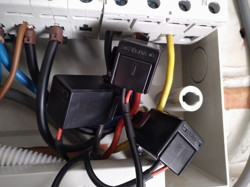
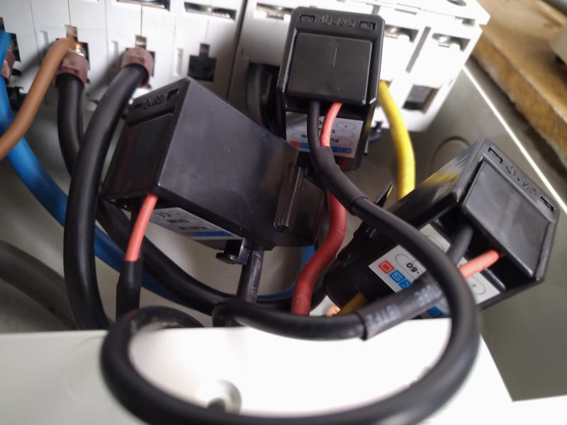
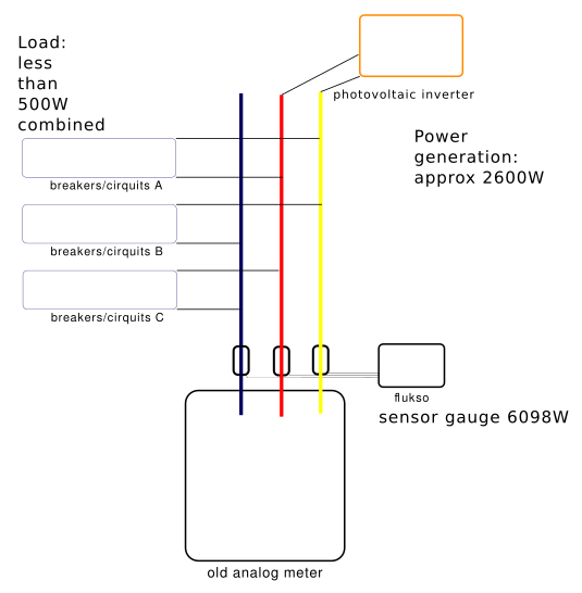
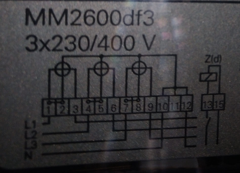
I have a FLM02B with three current clamps on a three-phase system (no neutral wire), with the load very roughly split over 3 pairs of phases and a PV inverter on one pair. (schema attached)
The flukso is set to 3-phase (was 1 phase before)
I'm currently measuring very high power passing through the clamps, like 6000W whereas only 2600W is produced and less than 800W is consumed. The analog meter is running backwards.
When switching the inverter off, the flukso's measurements are within normal range (800W). After switching the inverter back on, the power appears to be realistic (having switched directions of course) for nearly a minute and then climbs back up to the impossible ranges. (logfile attached)
Is it even supposed to work in this condition? Am I doing something wrong?
(The clamps are tightened to a click. I couldn't avoid having the wires running from the clamps to the flukso close to the power wires for a few centimeter, but I minimized all other contact. The flukso is up to date (revision 250) and is fed with the original power supply and appears to be working fine otherwise. The number of clamp ports is set to three and the number of phases is set to the same. The inverter is a cheap chinese Sununo Plus 2.5K "transformerless")
| Attachment | Size |
|---|---|
| log-na-onderbreking-inverter-short-gauge.txt | 12.08 KB |
| installation1.jpg | 104.83 KB |
| installation_2.jpg | 69.83 KB |
| pv-installatie.png | 37.44 KB |
| IMG_20210324_124810.jpg | 933.15 KB |
| IMG_20210324_143923.jpg | 95.53 KB |
Looks like you have an old 3x230VAC network without neutral wire.
My guesses and advice:
- 3phase setting is OK
- I think you should put the voltage setting to 230/sqrt(3) = 132V (=phase voltage of an old 3*230VAC without neutral)
- flukso 02B cannot measure the direction of the power. So connect your solar production between the current clamps and the analog meter (let it do by a professional if you aren't). Now it messes up your measurement during daytime. Then you only measure consumed power.
- Optional: Put a pulse counter on your PV circuit to measure solar production.
Thank you Bram, I just changed the config and will see what it does tomorrow.
Did it work?
I'm afraid it didn't work. The measurements are lower (obviously) but still incorrect. (I counted the meter's spinning disk, the reported output of the solar inverter, it's reported voltage (negligible) and the live measurements from the flukso.
But the plot thickens: at night I should have a base load of 65W (I know, I'm working on lowering it) plus one modern freezer and one modern refrigerator. The solar inverter turns itself off. Yet the flukso reports a throughput fluctuating between 450 and 550W for the entire night!
The wires between the clamps and the flukso have to run through the same slot as the main source from the meter for practical reasons. They are thus very close to the 3phase wires. I could remove the face plate of the breaker box, undo the whole clamp setup and lead them out straight into thin air.
Also I have an old oscilloscope, I could stick it across the leads of the clamp and see what comes out?
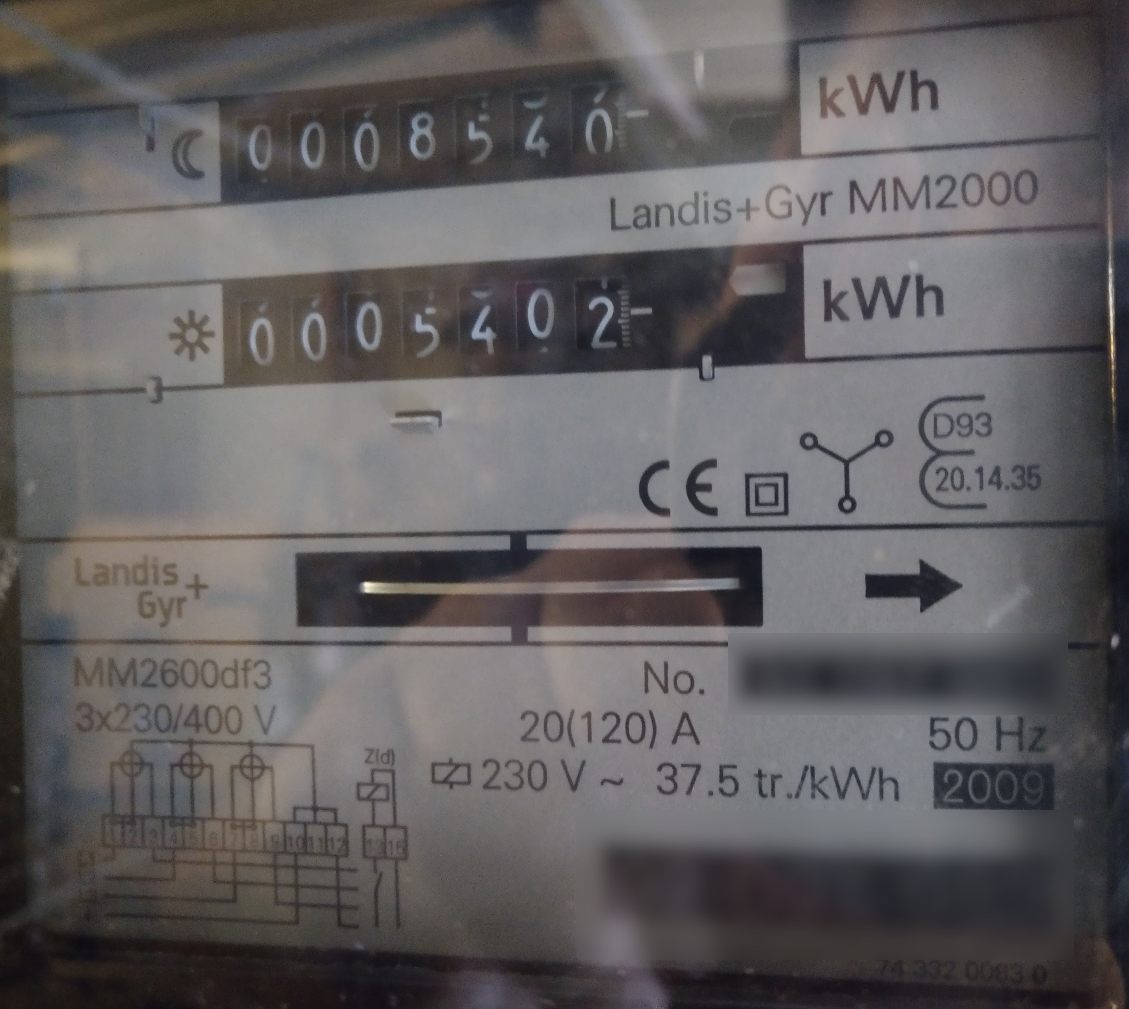
(I'm trying to attach a picture of my meter to this post, give me a moment)
The pictures of the meter are now attached to the opening post of this topic (IMG_20210324_124810.jpg and IMG_20210324_143923.jpg)
Inverters tend to have a bad power factor; it has shown in the past that using current clamps for inverter current measurement is a bad idea; go for a pulse counter instead - and make it a separate input though; all all matter of wiring - see https://energyhacks.wordpress.com/2014/07/10/wire-to-measure/ as a source of idea.
Gebhardm: Thanks, but that's not the issue at night ;-) Also I'm not trying to measure the throughput of the inverter, I'm trying to get the connection between the supply net and my whole house including inverter. (I can get a reasonable feel from the inverter by polling it's digital readout)
On phantom loads see also https://www.flukso.net/content/phantom-loads
Okay, I had some quality one-on-one time with the breaker panel after the wife went to bed.
There are two circuits drawing 50W as measured by the fukso. But the big one appears to be the UPS: the consumption measured by the flukso dropped by 190W whereas the UPS itself repots using 60W.
I still have quite a bit unaccounted for, but ran into wifi issues.
Gebhardm: thanks for setting me on the right path!
Can a newer FLM measure the power factor? Currently my setup is rather useless ;-)
It isn't useless as a bad power factor has also to be accounted for ;-) I am still doing research myself on how to cure these zillions of bad power supplies - on an LED lamps from Philips was written PF 0.5 - that is a shame!
This makes me think I should run a few DC lines for low(er) power applications. Rather than having 20 bad led psu's I'd like one decent big one. Tesla is turning in his grave...
My understanding is that the issue's root cause is the always on nature of these devices; so I tend to spend real switches and use these PSUs only in case they are needed - as such an "off" light-PSU by light switch is not an issue, but the "not off, off night lights" of, for example, IKEA origin... Or, as written, a PV inverter with an nightly private life ;-)
Is there a flukso-like product that can read trueRMS values in a 3-phase without neuter setup like mine? It doesn't have to be clamp-metering but I'd still like to know what/when I'm consuming.
To answer my own question, it seems like Open energy monitor has a suitable product with power factor approximation! (https://shop.openenergymonitor.com/emontx-energy-monitor-transmitter/)
Joris,
,
I read this on github mabey this is your issue:
Having a mix of 3-phase and single-phase loads in a 3x230V without N requires a compromise on accuracy. You may hook up two clamps, one on the "black" and one on the "brown" phase. Configure the Fluksometer as 3-phase with a 230V voltage. This will cause a measurement error for any 3-phase load, for example an induction cooker. Instead of 3*amps*133V = 400*amps (W) the Fluksometer will register 2*amps*230V = 460*amps (W) for the induction plates, or a 15% deviation.
So, if only two phases are used, with the third one acting as neutral, then two clamps on the used phases will work, with some compromise in accuracy when a 3-phase load is active. Putting a clamp on each phase and configuring the voltage as 133V will only yield correct results with a true three-phase load.
I came across the same problem (3x230V without N and observing high power readings). The explanation of MichaelVDK makes sense but I don't see why it is not possible to compute the loads correctly? The measurements are there, right?