Hi,
I've had my Flukso FLM02a for over half a year now, but I can't seem to get accurate electricity measurements out of it. I also measure water usage via pulses - and that works like a champ!
We have a 3-phase setup at home (3x400+N), and so I'm using 3x 50A clamps on the phases.
I had initially configured the setup as 3 clamp ports, 1 phase - in order to make sure I had valid measurements of each phase (initially one wasn't registering at all - badly cabled). I had also set the voltage at 230V/50Hz, which I think is correct for my setup (I measure ~230V between a phase and N, and ~400V between phases).
Most usage in our home can be attributed to single-phase devices : our 150L water boiler, washing mashine/dryer, microwave, etc. In fact the only 3-phase device we still have is our oven (we used to have a water pump).
Regardless, I wasn't getting good values at 230V. I first checked and double-checked the cabling, but it looked good - and was providing measurements. Then I had an idea: since voltage seemed to be the only variable I could influence in the configuration, I played with it a bit until the power values were more reasonable (I know the wattage of most devices via my Plugwise setup, for example our boiler is currently just under 1kW). But the total still seemed off...
So, last week I had figured: why don't I calibrate the voltage per phase (still assuming it could be used as a correction factor... but I'm obviously no electrician!)... and I took a fan heater, measured it to be sure the power was more or less constant (1166W), and tweaked the voltage sensor config on each of the 3 phases until the flukso was also showing that power usage [delta] on every phase. I ended up with 383V (phase R), 275V (S), 455V (T). I don't know if my line of reasoning here is correct...
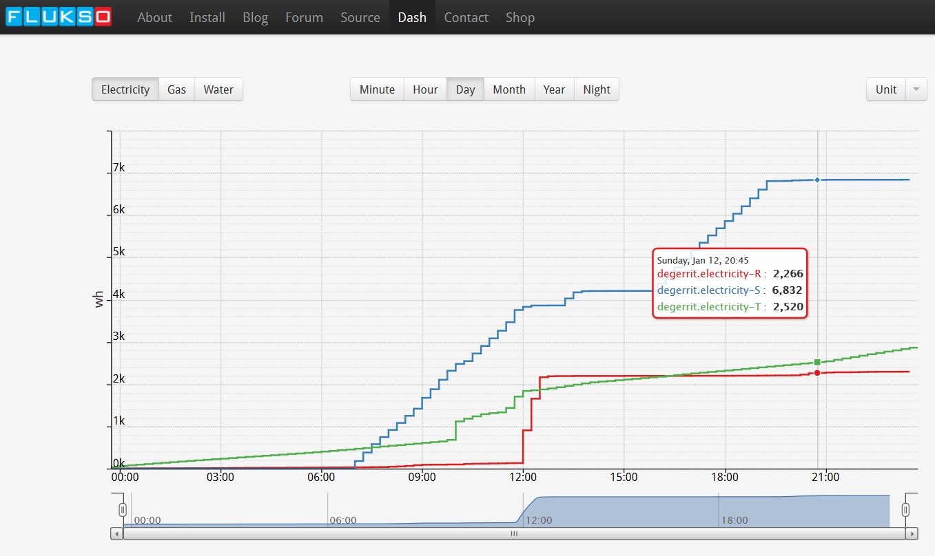
Then I wrote down the electricity counter at midnight last night, and again today at 20:45 - with the intention to compare with my Flukso's readings.
Boy was I disappointed: my meter measured 60333,2 - 60315,8 = 17.4 kWh for that period, and Flukso, using "Wh [cumulative]", measured RST values (2266+6832+2520) - (2+0+62) = 11,6 kWh. Another giveaway that the measurements were off here, looking at the Dash: our 1kW boiler on phase S (>7AM) is showing only 700W.
Oh, and one more oddity on Phase S : although most of our bulbs are CFL bulbs - I have a few incandescent bulbs (pf=1?). Turning on 3 of them (180W) - doesn't even show as much as a blip (using Energy Control on Android to visualise the instant power use). I've not tried this on the other phases, but our TV setup on another phase does register.
Does anyone have any advice for me? Is my Flukso faulty? Is my cabling faulty? Are my assumptions faulty?
Thanks for any tips!
- Gerrit
----
[UPDATE 27/1/2013]
OK, so it turns out my clamps were not completely shut (see comments). I leave the above for reference - but it's all based on a bad installation!
| Attachment | Size |
|---|---|
| flukso-benchmarking-end.jpg | 218.55 KB |
| 1-PC152443.JPG | 308.19 KB |
| Flukso_Benchmark_3_wattages_BAD.png | 10.14 KB |
| Flukso_Benchmark_3_wattages_UPDATE.png | 8.95 KB |
| flukso troublshooting measuring 2014-01-UPLOAD.xls | 150 KB |
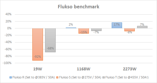
Update: I did some more "benchmarking" of the 3 phases using a few devices - attached the Excel and PNG file above. Again, this is using *fake* pseudo-calibrated voltages...
- at 20W I get deviations of -70% to -90%. Low power devices hardly register at all.
- at 1200W I get deviations of -15% to +2%.
- at 2200W I get deviations of -8% to 17%
Some devices (I guess those with low power factor are even much worse).
My conclusion is that the setup with 3 clamps here is pretty useless. I think the only way to go would be to spend some more cash on a DIN rail power meter.
Again, unless I am doing something very wrong... I'd be happy to be enlightened!
I guess, we are getting down on the physical foundations of current clamp measurement and it's assumed accuracy... If you look at the current clamp specification you see that the "quality of measurement" is somehow depending on the time it takes until a current clamp detects a current; for the used clamp type it shows 300ms (0.3sec!!!) - this is "no issue" on a continuous resistive load, but I guess it becomes an issue on high-frequency power consumption as produced by a modern switched power supply (therefore especially HAM radio amateurs "love" these power supplies); also we have seen the issue with PV's reactive power consumption. So, my onclusion is to take the measurements of my current clamp installment not literally, but as an indicator where the large holes are... Accuracy in the sense of comparable results to the supplier measurement one can reach only with the invasive installation of an S0 counter - but that was not intended with the clamps...
So, yes, I also see the discrepancies, but am not to picky about it.
Best regards,
Markus
I think that the current clamps that are in the shop here on Flukso.net pushes the limit lower because it let people doing there FLM installation very easy that way, almost everyone can do it. And let that be a major point in accessing such metermonitoring. I saw other more expensive systems on the market.
Of course, you’re free to install SO kWh meters. Saw them on ebay for 16 € /piece for (5)65 A...
Even i think about it to put one, but in my fusebox is not much space left and should be rewired witch if bad because now it is very clean and nice. It will become messy.
Talking about accuracy : my induction cooking plate if off en there is still a consumption of 100 - 110 watt !
If i check with a consumption meter direct in the 230 V socket (sic..) it shows less than 1 watt !
Reactive power - the same issue as with PV installations; to compensate this with a current clamp is tricky, thus expensive...
Markus, what do you mean with tricky and expensive with a current clamp ?
Thanks for your feedback, guys. I admit that I was initially misguided by previous forum posts stating error margins of 2% difference - but never saying that's in "lab-conditions".
But regardless, still some things puzzles me.
If I follow the user manual and set my voltage to the actual 230V for each phase - then my Flukso readings are even more off than in my pseudo-calibrated setup. Why would I even need to mess with that number?
Yes, it's quite clear many of my devices must have switched power supplies which are impossible to reliably measure this way (including my vacuum cleaner!).
But surely my fan/heater, which is basically just a big resistor, should give reliable readings. And so should our 150L boiler, which is our largest "user". And then, my 3x60W incandescent light bulbs - there is no discernable load on that measured phase R before I turn them on, but it doesn't measure at all. Surely this does not have a switching power supply! :-)
Could this mean that the mere presence of CFL light bulbs and switching power supplies on a phase influences/distorts readings of other devices?
Are the clamps influencing each other (though I wouldn't say so from the graphs)?
Is it worth swapping the clamps around to experiment further?
@Fluc: I don't know how they do it, but following quote from http://en.wikipedia.org/wiki/Current_clamp lets me assume that arithmetically some higher sophisticated methods are available (Fluke, for example, sells some very expensive current clamp measuring equipment); but this means either different integration of the current clamps themthelves (electronically) or a huge amount of software based analytics with the correspondingly necessary resources - sadly I studied the wrong discipline being no electrical engineer (or is it eclectical engineer ;-)). Here the quote:
Current clamps are usually used to read the magnitude of a sinusoidal current (as invariably used in alternating current (AC) power distribution systems), but in conjunction with more advanced instrumentation the phase and waveform are available.
This also implies very quick reaction time of the clamps as well as a method to detect and interpret the actual measurement - this is like the often misunderstood difference between Watts and Watthours, so a function and its integral over time...
@degerrit: One additional idea is "trouble with the clamps impedance"; in the setup within the FLM a voltage divider brings down the delivered 0 to 5 V per 0 to 50 (x) A into the range of the microcontroller's needed analog reference voltage that is set to 1.1V (by a 1k91 resistor); so, if the actual impedance of the clamp does not match the given voltage divider then Ohm's law is brutally implying wrong numbers. But this is just a guess and hopefully not an issue (as it would not be the first time that a supplier slightly changes specifications). A calibration option in the configuration would cure this to a certain extent, of course (as long as the voltage mapping is applicable on the hardware side).
But this are all my wildest fantasies...
Best regards
Markus
Interesting page from a similar 'competitor' to Flukso - they do have a fairly advanced calibration option:
http://www.openenergymonitor.org/emon/modules/emontx/firmware/calibration
Since that device seems to be using comparable technology as Flukso, I guess it's relevant to this discussion.
On the one had, they talk about a CT clamp calibration, within a range of about 5% (I think this is, ballpark figure, also the claimed accuracy of the Flukso), but they're also talking about a voltage, current and phase shift calibration. I haven't looked deeper into it, but my guess is that that device would perform equally bad for switching power supplies or bad pf factors (?) - because it also uses a CT clamp.
Can anyone comment on this calibration relevance for Flukso?
I guess for voltage and current - this is done in the Flukso sensor configuration page?
I'm not educated enough in electricity to understand the impact of "phase shifts" in terms of Flukso metering...
@Markus - finally, back to the CT clamp - would the theoretical problem with clamp impedance be something I can measure on the Flukso pins with a voltmeter? I guess if there is a significant load on a phase, say 2000W, I should get a fairly predictable voltage somewhere under 5V - correct? And this would prove or disprove that idea?
By my knowings there is no calibration possible inside the Flukso fot the CT clamp. Perhaps you can put a small potentiometer on the analogue input (value ?) but this should only work if you have always to high values, comparing the real consumption. You can not calibrate the power factor because this depends on your load.
The output DV voltage of the CT clamp shall be linear to the CT clamp size and input, so : 0 to 5 V/DC output ~~> 0 to 50 A/AC input. But once you connect the + and - to a analogue input, this DC voltage drops because there is a internal resistance in the FLM itself.
The calculations in the firmware of the Flukso do the rest to have correct values i think.
Not sure how this work i'm afraid...the help of others is appreciable ;-)
Egad! I had some time, so I tried swapping around clamps, and clamping N as well - and to my suprise, because I am sure I checked this, I found that the clamps were not completely clicked closed - even the clamp reporting the best values.
After 3 'clicks' - the instant (per-second) power measurements almost doubled as a result! So now I also set the voltages back to more 'sane' values.
I'll have to re-do my calibration - but I'll be sure to post some results!
My advice for newbies such as myself would therefore be to make sure you practise your clamping skills in before you move the clamps to your power closet ;-)
Because there seem to be some things mixed up, a little bit of education or high-school knowledge fresh-up: It is all about Ohm's law - U/I = R with U voltage, I current and R resistance.
The clamps delivered with my FLM have an impedance, an inner resistance of the sensing coil at no load (note: coils are digital electronics nightmare as "impedance Z" is only "partly equal" to R having an imaginary part...), of 6.9 kOhm (@degeritt: you can measure this with a voltmeter that has also a resistance measuring option; but do this with the clamps not being connected or being under load!!!)
In the FLM there is a resistor of 1k91 Ohms parallel to the clamp's 6k9 Ohms. Now with Ohm's law:
What does the clamp do? At 50A the clamp delivers 5V this equals 5V / 6k9 Ohms = 0,000725A.
What happens in the FLM? The parallel resistor to the clamp reduces the overall resistance of the clamp towards the FLM's analog-digital-converter: 1/Rtotal = 1/R1 + 1/R2 or (6900*1910)/(6900+1910) = 1496 Ohms
U = R * I => 1496 Ohm * 0,000725A = 1,085 V at 50A which is basically the configured maximum reference voltage of the FLM's ADC... (more about this in the corresponding Atmel datasheet)
Consequence: If the impedance of the current clamp (the 6k9 Ohms) does not match above calculation, this will directly lead to an erroneous value.
So, for calibration there are two options: A software part that could shift the measurement range (introducing an overall measurement error) and a hardware part that does the alignment of a clamp with the FLM actually affecting the voltage divider (the internal resistor) - hopefully the clamp supplier sticks to the specified impedance though...
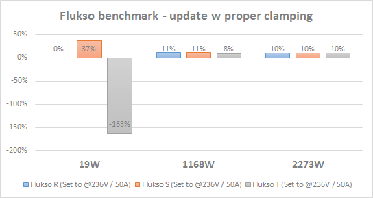
[UPDATE 27/1/2013]
OK, so it turns out my clamps were not completely shut. This had the effect of a cutoff at low amperages, and at higher amperages gave variable results per phase (I guess, depending on the state of the clamp).
After correcting this - I'm now getting much more consistent readings, except at really low amperages and/or with non-resistive loads. I've updated the tables and graphs above. I'd still like to compare with my meter, but initial tests showed also an acceptable deviation.
All in all - I'm satisfied : +/- 10% accuracy (I can probably get it even lower by adjusting the voltage parameter), finally! predictable readings also for simple things light 60W light bulbs.
Overall, I can now use my Flukso as I intended : to monitor household electricity usage, and to monitor equipment that's otherwise impossible to measure (hardwired things like water pumps, or indeed lighting). I'm a happy camper!