I recently installed a FLM2. I have a 3 phase installation (belgium) and 3 clamps attached on the 3 phases (checked by my electrician and according to him right attached).
Configuration FLM: 3 phases - 3 clamps 50 A - 230V
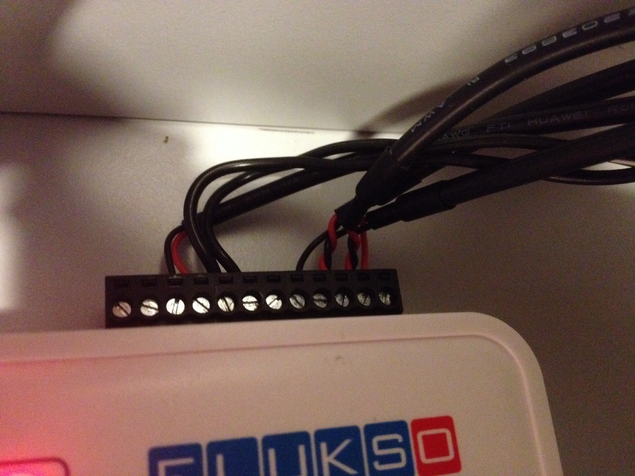
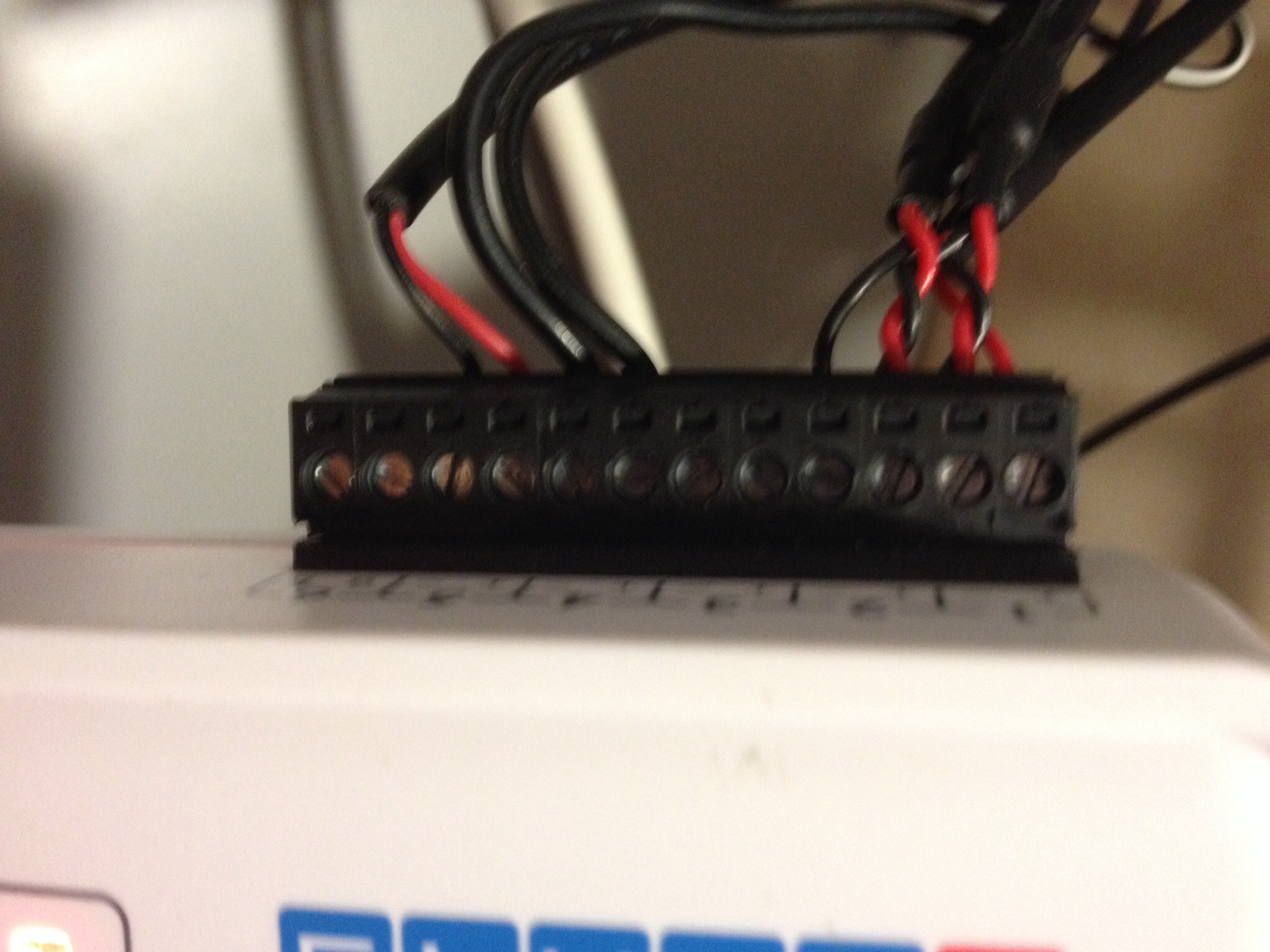
Connection clamps in serie (so no wires on port 3): see attached photos
Problem: the measuring is much too low. For instance: yesterday i measured 8,018 kWh on the FLM while the official company meter indicates a consumption of 13,430 kWh.
What can be wrong here?
Thx for the help.
Joost
| Attachment | Size |
|---|---|
| image.jpg | 935.73 KB |
| image.jpg | 743.39 KB |
What do you mean by "clamps in serie"??? The picture looks rather strange for a three-clamp-installation; the intended wiring is
The installation as shown in the images is not correct for a 3-clamp-installation! I guess, you have pulse counters on Terminal 4 and 5 - these are connected correctly; the same should also apply to terminal 1 to 3.
Fatty fingers - and still no edit in the forum....
Indeed, Gebhardm, port 4 is a solar DIN rail kWh meter and port 5 is the gasmeter. For the 3 phase consumption i referred to the following post in this forum "6-position screw terminal":
"A three-phase Fluksometer with a 6-position connector will have its clamps connected in series. So clamp 1 will be on positions 1(+)/2(-), clamp 2 on 2(+)/3(-) and clamp 3 on 3(+)/4(-). Positions 5(+)/6(-) are again reserved for attaching a pulse output to the Fluksometer."
The wires in my situation are put in this position.
Isn't that correct?
?! from the image I detect the following:
screw 1 (which is terminal, better input 1 +) - red cable
screw 2 (which is terminal, better input 1 -) - drilled black and red cable WRONG
screw 3 (which is terminal 2 +) - drilled black and red cable WRONG
screw 4 (which is terminal 2 -) - black cable
screws 5 (t3+) and 6 (t3-) open - WRONG in a three clamp setting - as this is the third input.
The (+) screws direct internally to the analog-digital-converter inputs of the microcontroller (via voltage divider), the (-) screws are on ground...
In each screw there shall be only one cable - "in series" here just means first clamp, second clamp, third clamp.
So, connect it correctly:
clamp 1, red cable screw 1, black cable screw 2 (as the signs printed indicate); clamp 2, red cable screw 3, black cable screw 4, clamp 3, red cable screw 5, black cable screw 6 and so forth...
There are 6 input terminal with together 12 screws, 2 for each input (as correctly connected for the pulse input); I would never had thought that this causes an issue...
https://www.flukso.net/files/flm02/manual.pdf --> page 1, chapter 1.1.1: The screw terminal contains twelve inputs. A port on the screw terminal is defined as a pair of adjacent inputs.
@GEBHARDM
Thanks for your help! It works!
Readings are much higher now.
Sorry for my confusion......
You probably got the connection info from this blog post in 2010. That wiring logic applied to an FLM01, which has meanwhile been superseded by the FLM02.
@ICARUS75 Indeed, Bart, therefrom my confusion....
I'm glad everything's OK now.
Joost