Fluksometer
We will in turn introduce the Fluksometer v3’s ports, button and LEDs. The Fluksometer v3 is currently available in a single ‘E’ version, a.k.a. FLM03E.
ports
- sensor ports
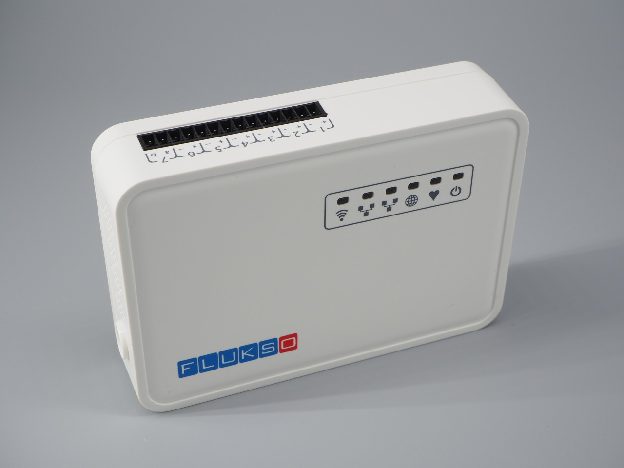
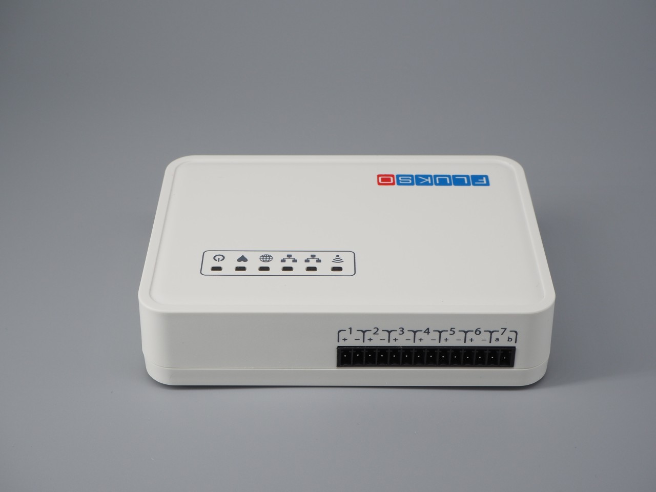
The screw terminal contains fourteen inputs. A port on the screw terminal is defined as a pair of adjacent inputs. The port numbers are printed on the front of the enclosure for easy reference, with the polarity denoted by + and -.
Ports #1 to #3 are current clamp ports that are tuned to accept Flukso FLS06-type split-core current clamps. Ports #4, #5 and #6 can be used for counting pulses. This includes support for the S0 interface (S0 is an open- collector interface standardized in DIN EN 62053-31) common to DIN-rail energy meters. Pulse ports accept Flukso water and gas probes as well. Port #7 can be hooked up to a NTA8130-compliant local P1 port found on Dutch smart meters. Contrary to the other ports, port #7 has its polarity indicated by the letters a (tx) and b (rx).
Note
The current FLM03E firmware still lacks the P1 port decoder. This functionality will be added in a future release.
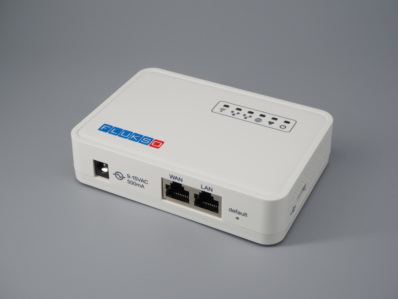
- ethernet
- Both ethernet ports support a 10baseT/100baseTx interface with auto- negotiation and auto MDI/MDI-X crossover detection. The right ethernet port (LAN) is meant for configuring the Fluksometer, while the left port (WAN) can be used as an internet uplink for the Fluksometer.
- power port
- While the power port can still accepts a 9-15V DC voltage, we now ship all Fluksometer v3’s with a 9V AC-AC adapter. The AC adapter acts as a power source to the FLM03 as well as the line voltage sensor.
- USB
- The USB 2.0 type A port on the right side of the Fluksometer can accept a 3G stick. This allows the FLM to make a direct internet connection, bypassing the LAN.
button
The pushbutton has a dual function. Which function will be triggered depends on how long the button is pressed. Make sure the heartbeat LED is blinking before using the button.
- Restore networking defaults
- If you press the button between 2 and 5 seconds, the Fluksometer will restore its default network settings.
- Restore firmware
- Keep the button pressed for between 10 and 15 seconds to restore the Fluksometer’s stock firmware, which is then followed by a reboot. You will have to reconfigure all network and sensor settings. Connect to the local web interface after the heartbeat LED starts blinking again.
LEDs
The Fluksometer has six red LEDs on the top of its enclosure. Together these LEDs provide an overview of the Fluksometer’s internal functioning, the status of its network interfaces and its ability to communicate with the Flukso server. From left to right, these LEDs are:
- Wifi
- If the wifi interface is enabled, the wifi LED will light up when the wireless connection is succesfully established. Network traffic crossing the wifi interface will trigger a blinking LED.
- Ethernet
- Both ethernet LED will be on when their respective ethernet links, WAN/LAN, are established. This can either be a 10baseT or 100baseTX link in full- or half-duplex mode.
- Globe
- After the Fluksometer has finished its boot sequence, the globe LED will be on when it can connect to the Flukso server via MQTT/SSL.
- Heartbeat
- The heartbeat LED is positioned right next to the globe led. While the globe LED informs us about the status of the Fluksometer’s external communication, the heartbeat LED allows us to monitor the Fluksometer’s internal health. This LED will be on when the sensor board is running its firmware. From the moment the flx daemon is started during the boot sequence, it will ping the sensor board every second. Each ping triggers a blink of this LED, thus mimicking a real heartbeat. Hence, a ’heartbeat’ is an indication of fully booted Fluksometer, an active flx daemon, a sensor board running its firmware and proper communication between the main board and sensor board.
- Power
- The power LED is directly connected to the internal 3.3V supply. A burning LED indicates that power has been applied to the device and the internal 3.3V voltage regulator is working properly.