Hi all,
I am trying to correctly install the FLM and played around with some of the clamps and have some problems finding the right wires. I have a single phase and a grid connected PV installation.
1. The clamp around the PV wire reads a constant of around 50-60 watt at night. I suppose the PV converter uses energy, even at night. If so, is it worth trying to turn it off at night and back on every morning to limit it's consumption?
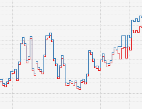
2. See attached graph. The red graph is the main power. The blue graph is the clamp around the PV wire. There is no change in the usage in the house in this interval. What is shows is the electricity generated by the PV installation feeded back to the grid.
Is it possible to connect the main clamp somewhere so that it does not measure the electricity generated by the PV? I would like to see the energy I use, not the energy I generated minus the one used (which is what I suppose I am looking at).
Thanks!
| Attachment | Size |
|---|---|
| blue_pv_and_red_main.png | 8.71 KB |
At 1) I assume that the PV clamp measures a (capacitive) reactive power; see https://www.flukso.net/content/solar-panel-measuring-not-accurate; there has been a lengthy discussion on that issue.
At 2) Where have you actually attached the clamps? I put mine for consumption reading directly after the first main fuse to measure all current taken from the mains (this is also after the official kWh meter from the mains side); for the PV installation I put the clamp (now a DIN-rail kWh meter with an S0 pulse output due to above issue) on the inverter's side before the fuse/kWh meter through that the PV current is fed back into the mains. This definitely decouples the both measure circuits.
https://www.flukso.net/content/solar-panel-measuring-not-accurate - it also took the semicolon for an URL part...
Do not use clamps for solar panels, use the S0 output from a Din rail meter.
Sometimes even a din-rail meter will measure a power generated at night.
Have a look at separating household consumption and generated power and fuse box wiring.
First, the PV measuring. Thanks to the feedback here I figured out I have a EM10-DIN rail meter (https://www.flukso.net/content/em10-din) with an S0 output and connected that one with on of the FLM pulse ports. It's dark here so will have to wait till tomorrow to get some feedback on this one.
Great to see the some good feedback for an electronics n00b in this community. Thanks all! I need some time to process the consumption vs generated power but that's for tomorrow. :)
I noticed I am not the only one with questions about the PV pulse metering so I collected the feedback in this discussion in a little blog post for future reference, hope it might help someone: http://suffix.be/blog/measure-photovoltaic-solar-output-flukso
See also the phantom load discussion and the reference to power factors; note that your measured 50 to 60 are actually the [VA] (volt amperes) apparent power.
Following the same calculation I get for my SMA inverter following impedance phase angle (refer to wikipedia AC power)
This means, the complex power is actually "purely reactive"...
During operation SMA claims that their inverters have a power factor of "1" - so no "reactive power" then...
you can also connect pvoutput.org to flukso.net for your solar system :
http://pvoutput.org/intraday.jsp?id=7597&sid=6123
There is also a decent Android app for pvoutput.